High performance node page: Difference between revisions
| Line 124: | Line 124: | ||
* Panel to Panel: up to xx km (10km?) | * Panel to Panel: up to xx km (10km?) | ||
* External to External: more than xx km (20-30km?), depending on antenna type | * External to External: more than xx km (20-30km?), depending on antenna type | ||
This one is still a bit of a problem. We need to find some very long open area to perform our distance tests. | |||
== Regulatory == | == Regulatory == | ||
Revision as of 22:28, 4 March 2009
What is a HPN (high performance node) ?
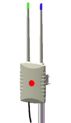
The HPN is a multi-radio (3x radios), high performance, wireless (802.11) router. It has three antennas, one 5.8Ghz directional panel antenna as well as two omni's (2.4Ghz + 5.8Ghz). At the bottom of the router there is a weather proof UTP connector that is used for both Power-Over-Ethernet (PoE) and Ethernet connectivity to the router. A special mounting bracket at the back of the router allows it to be attached to an aluminum pole that is usually mounted to the side of a building or some structure.
How to build a mesh with HPN's
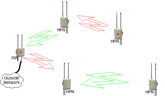
The idea is to build a mesh network with these routers by aligning each directional antennas to point to a neighboring omni or another directional antenna. The wireless cards in a router operates on different channels (frequencies). To make it more user friendly each channel (frequencies) is tied to a color. This means that a red panel antenna must be aligned to a red omni (or another red panel) and a green panel must be aligned to a green omni (or green panel). The blue channel (2.4Ghz) is used to create a wifi hostspot for clients who would like to connect to the mesh network via wifi.
Every mesh network usually have one GateWay that connects to the Internet or to some other network. Any one of the mesh nodes can be configured to become a GateWay for the mesh. When a node becomes a GateWay then the channels (frequencies) of the antennas are fixed to the following: 5.8Ghz directional panel = RED, 5.8Ghz omni = GREEN and the 2.4Ghz omni = BLUE. The GateWay node will also become the DNS server for the mesh and all the nodes inside the mesh will register their HostNames with the DNS server. Another function of the GateWay node is to act as a time server for the mesh network and all the nodes inside the mesh will synchronize their time with the GateWay.
The best approach to build a mesh network is to start with the installation of the GateWay node. Next you install the node(s) that aligns to the GateWay node and then grow the mesh from there. Fist perform a visual alignment of the panel antenna on the node before the power is switched on. When a normal node starts up for the first time, then it will hunt for a mesh signal and it will lock it's channels (frequencies) once connectivity is established. It will first hunt for connectivity on both the red and green channels on the directional panel antenna for X seconds. If no signal is found, then the hunt will continue on the 5.8Ghz omni directional antenna for X seconds. This sequence will repeat itself until a signal is found, or until the channels are manually locked via the web interface on the node itself.
Every node has a GREEN and a RED LED that is visible from underneath the node (should be visible when one stands under the node that is mounted on a pole). These LEDs are there to give some indication of connectivity and they will only turn on if connectivity can be established on either the red or green channel. Note that the LED does not show the signal quality or to what node it is connected to, it only shows that there is connectivity on that channel. Signal quality and node connectivity information is only available via the web interface, but in most cases a visual alignment combined with a link indicator will be sufficient enough to get a mesh node up and running.
How can a client connect to the mesh
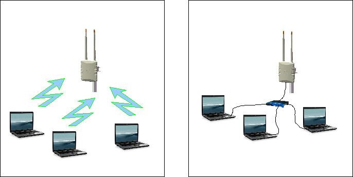
Client devices can connect to any of the nodes via Ethernet or via wifi (blue channel = hostspot). The client devices should be configured to make use of DHCP so that all networking configurations can be done automatically (The node will provide all the networking details via DHCP). It is also recommended that the IPv6 protocol stack should be switch on if it is available. IPv6 should already be enabled on Windows Vista as well as most Unix systems.
How does the mesh work ?
Almost everything in the network will be configured automatically, except for the selection of the gateway node and the channel (red or green) of a wireless link. The mesh supports both IPv6 and IPv4 traffic from any end-point (a place where a mesh client connects) to any other end-point in the mesh, while the backbone uses IPv6 only. A routing protocol called OLSR (Optimized Link State Routing) is used to exchange routing information between all the nodes inside the mesh and to select the best path for data traffic between end-points in the mesh.
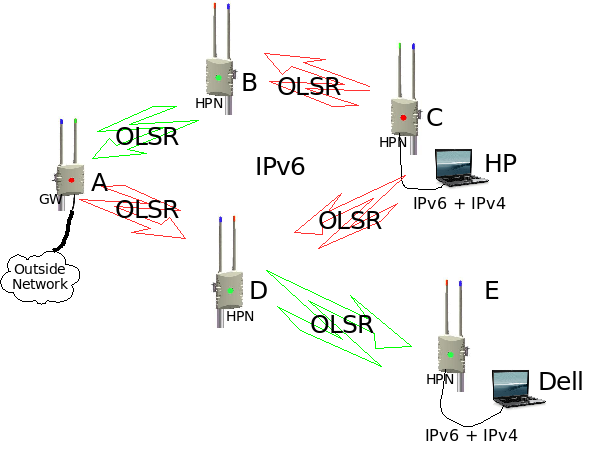
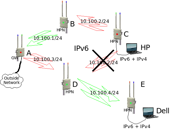
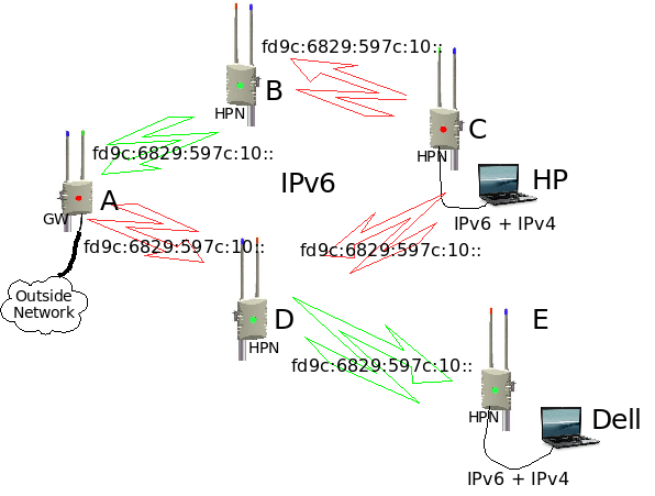
Lets take an example (see diagram) where HP want to send data to Dell.
Using IPv6
HP will address the data to the IPv6 address of Dell and send it to node C. Node C will look in it's routing table and see that there are two routes to Dell, one route via node B-A-D-E and the other route via D-E. It will then select the best route and send it to the next node, in our case node D. Node D will look in it's routing table and see that the only route to Dell is via node E. Node E will look at it's routing table and see that Dell is directly connected and it will forward the data to Dell.
Using IPv4
This one is a bit more complicated. IPv4 is only used on the outside of the network (where the mesh clients connect to it) and then the IPv4 traffic is tunneled over the IPv6 backbone of the mesh to any another end point in the mesh. The mesh will automatically create a one-to-many IPv4 tunnel over the IPv6 network (4over6 tunneling protocol). This means that it looks like a network with an IPv4 tunnel from every IPv4 subnet to every other IPv4 subnet in the mesh. From a client's perspective it looks like a normal IPv4 routed network. From the backbone's perspective it looks like a IPv6 only network and all the OLSR routing information is IPv6 only.
So how does the network know how to forward IPv4 packets to the correct destination ? It makes use of IPv4-mapped-IPv6 addresses (see RFC4291 and RFC4038). Every node will map an IPv4 addresses into a IPv6 address before data goes to the backbone and the IPv4-Mapped-IPv6 addresses are converted back to a plain IPv4 address when it comes out of the backbone. OLSR will advertise these IPv4-Mapped-IPv6 address subnets on the backbone so that all the nodes will learn these subnets and they will calculate the best route to these subnets.
Lets take example again, using IPv4. HP will address the data to the IPv4 address of Dell and send it to node C. Node C will change the IPv4 packet to an IPv6 packet with an IPv4-mapped-IPv6 addresses. From there it will follow the same route as the IPv6 example above. Node E will take the original IPv4 packet out of the IPv4-mapped-IPv6 packet and it will send the original IPv4 packet to Dell.
See http://wirelessafrica.meraka.org.za/wiki/index.php/John%27s_research#4over6_Automatic_tunnels for more detail of the 4over6 tunneling protocol.
Why is the mesh using IPv6 ?
Reason one
It is predicted that unused IPv4 address space will be depleted within the next two years. Operating systems like Vista and most Unix systems defaults to IPv6 by default and most applications are IPv6 ready. With this in mind it makes sense that any new networking products should provide both IPv4 and IPv6 support.
Reason two
In a single radio mesh network there is just one RF channel and everybody makes use of the same IP subnet. One limitation of a single radio mesh is that each mesh radio needs to handle both incoming and outgoing traffic. This causes the throughput to be halved because a radio cannot transmit and receive simultaneously. Another problem is that if one radio is transmitting then all its neighbors must all be in listening mode. These problems can cause a single radio mesh to very quickly run out of steam.
Multi-radio mesh technology solves this problem by configuring every radio inside a router to operate on a different frequency and on a different IP subnet. In the HPN two radios are dedicated for backbone traffic and the third is used to create a client hotspot. 802.11a is generally used for backbone traffic, and 802.11b/g for client coverage.
In a multi-radio mesh network it is very difficult to use the same IPv4 subnet on all the backbone wireless interfaces inside a mesh. The OLSR routing protocol uses broadcast packets to flood OLSR routing information to all of it's neighbors. This works very well with a single radio mesh, but not with a multi-radio mesh. Almost all TCP/IP (IPv4) stacks implementations can only send out broadcast packets on one interface at a time, but not on multiple interfaces on the same IPv4 subnet. This means that every interface needs to operate on a different IPv4 subnet, with the effect that some OLSR links may be physically possible, but it cannot be used for data because the IPv4 subnets are different. A multi-radio IPv4 OLSR network is possible, but it usually needs a lot of planning and configuration.
The TCP/IP stack of IPv6 does not make use of broadcast packets and OLSR routing information is flooded to it's neighbors via multicast packets. These multicast packets will automatically be duplicated by the TCP/IP stack and send out via multiple IPv6 interfaces on the same IPv6 subnet. This means that the mesh can use the same IPv6 subnet, all over the mesh backbone, without any problems. With a multi-radio IPv6 OLSR mesh you don't need any IPv6 configuration on the backbone as all the nodes use the same IPv6 subnet.
Behavior of a normal node in a mesh
The following describes how a normal node will behave inside a mesh and what service it will provide:
- When a new node boots up for the fist time, then it will will go into a hunting mode and it will search for other nodes in the mesh. In hunting mode it will first configure the patch antenna on the GREEN frequency. It will perform a link local IPv6 ping on that interface for about X seconds to determine if any IPv6 connectivity can be found on that antenna/channel. If no connectivity is found after X seconds, then it will hunt further using RED on the patch, then GREEN on the omni and then RED on the omni. If no connectivity can be found, then it will start the hunting process from the beginning, or until it is manually locked via the WEB interface. If connectivity can be established, then it will enable the green/red link LED on the bottom of the node to show connectivity (use the WEB interface for more information on to witch node connectivity has been established to). If connectivity is lost then the LED will be off again. After stable connectivity for about X consecutive pings, then the node will lock the antenna/channels util someone changes it manually via the WEB interface. Once the antennas are locked then it will also change the sensitivity of the link LED and it update the LED less frequently. The LED sensitivity can be manually changed via the WEB interface by selecting the "alignment" button. The alignment feature will give signal strength information on the WEB interface.
- When a new node boots up then a unique IPv6 address ((inside this mesh. See IP addressing section) will be configured on all the Ethernet and wireless interfaces. An unique (inside this mesh) IPv4 address is calculated and configured on the Ethernet interface and on the 2.4Ghz omni interface. The node will use the MAC address of every adapter to calculate a unique IPv4 and IPv6 subnet for all the interfaces. These automatic addresses can be changed via the WEB interface (E.g. if a globally routeable IPv6 address is required for a website inside the mesh that should be visible from the Internet). Wireless interfaces are placed into adhoc mode and the channel, ssid and bssid are also configured.
- When a new node boots up the OLSR daemon is started and will listen en send OLSR topology packets to all it's neighboring nodes. OLSR runs on all the wireless interfaces, but not on the Ethernet interface. All the IPv4 subnets are converted to 4in6 IPv6 addresses and they are placed into the HNA section of olsr.conf, together with the IPv6 subnets that are configured on the Ethernet interface and on the 2.4Ghz omni interface. These HNA subnets are then distributed, via OLSR, to all the other nodes inside the mesh.
- 4over6 tunneling
- The node will start ntpd daemon on provide NTP time services on all it's IPv4 and IPv6 addresses. NTP will also synchronize it's local time with the GW-node on a regular basis.
- The node will register it's own hostname in DNS on the GW-node. It will start dnsmasq daemon and it will also provide DNS services on all it's IPv4 and IPv6 addresses. Dnsmasq will forward all DNS queries to the DNS server running on the GW-node.
- Dnsmasq is used to provide IPv4 DHCP services on both the Ethernet interface and on the 2.4Ghz omni interface.
- rtadvd will run on both the Ethernet interface and on the 2.4Ghz omni interface and it is used to advertise IPv6 prefixes to locally connected IPv6 client devices.
- sshd
- watchdogd
- mini_httpd
Behavior of the GateWay node in a mesh
Any standard mesh node can become a GateWay node by selecting the "GateWay" button under "Additional features" on the WEB interface. The GateWay node is the place where the mesh will connect to some outside network and it will be the default route for the mesh. When a normal node becomes a GateWay node, then it does not disable any normal node features, but it just adds some additional features. The following are the additional features that a GateWay node will have:
- The GW-node will not go into a hunting mode and it will lock it's channels with GREEN on the omni and RED on the directional panel. The default channels can be swapped via the WEB interface.
- The GW-node is the default route for the mesh and it will advertise a default route via OLSR to the rest of the mesh.
- The GW-node connects to the outside networks via Ethernet. It will perform a DHCP request on this interface in order to get an automatic IP adress and external DNS server configurations from the external network. These setting can also be overridden under "Additional features" on the WEB interface.
- The GW-node becomes the DNS server for the mesh and it will configure and start the named services on IPv6, on a well known IPv6 address of fec0:0:0:ffff::1. It will allow any node inside a mesh to submit their hostname into DNS and it will provide DNS services to any node or other device inside the mesh on IPv6 only. The GateWay node will also forward external DNS requests to upstream DNS servers if they are available. Upstream DNS servers are usually configured via DHCP but these setting can also be overridden under "Additional features" on the WEB interface. DNS services are still available via dnsmasq, on all it's IPv4 and IPv6 addresses like a normal node will do.
- The GW-node becomes a time server for the mesh. It will synchronize it's time to an external time server if it's configured and available, otherwise it will use it's own internal RTC to synchronize to. This time will be available to the rest of the mesh on a well known IPv6 address of fec0:0:0:ffff::1 and all the nodes in a mesh will use this time to synchronize their own time servers to. The GW-node will still provide NTP time on all it's IPv4 and IPv6 addresses like a normal node will do.
- The GW-node becomes a software update server for the mesh. It will start ftpd services on IPv6, on a well known IPv6 address of fec0:0:0:ffff::1. It will took for new software on the internet. If new software is available, then it will download the software and make it available to the other nodes inside the mesh to update with.
IPv4 addressing scheme
IPv6 addressing scheme
WEB interface
Specifications
High_Performance_Node_-_Specification
Typical Outdoor Range at 5.8Ghz
- Omni to Omni: up to xx km (1.5km?)
- Panel to Omni: up to xx km (5km?)
- Panel to Panel: up to xx km (10km?)
- External to External: more than xx km (20-30km?), depending on antenna type
This one is still a bit of a problem. We need to find some very long open area to perform our distance tests.
Regulatory
ICASA approved wifi adapters.
Using WEP/WPA in adhoc mode
One of the requirements of the High Performance Node is to have WEP or WPA enabled between the wireless links of the mesh nodes. This is one of the functionalities that we would like to sort out before we install any of the nodes in the field. It's very difficult to change the encryption mode after an installation because the mesh nodes will lose connectivity if one node is upgraded to use WEP, while another is still using older software without WEP.
WEP and WPA are both methods to enable the encryption of data that it is send over the air. WEP (Wired equivalence privacy) is an older standard and it makes use of a WEP encryption engine while the newer WPA standard added the use of an AES encryption engine. WEP encryption has some security flaws embedded into the protocol and there are several tools available on the Internet that can crack WEP keys. These tools are more effective with the cracking of 64bit WEP keys than with 128bit keys and they require a large amount of captured data and processing power to crack a key. Note that not all WEP keys can be cracked, but only weak keys and that flaw was addressed and fixed by WPA.
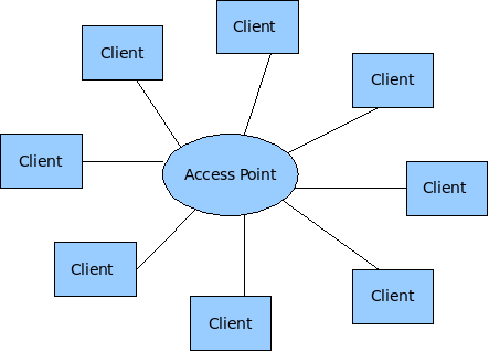
Wireless adapters on Unix Systems can operate in three different modes: Client, Hostap (Access Point) and Adhoc mode. Most of the implementations of wireless (802.11) networks are based on a model where there is one Access Point with several wireless clients attached to to it.
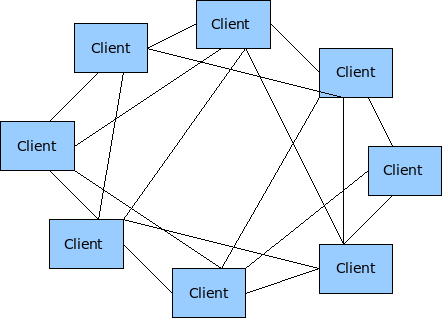
Wireless Mesh networks make use of the less tested Adhoc mode of 802.11.
WEP and WPA requires a couple of kld's to be loaded before they can be configured. The following kld's should be added to loader.conf
wlan_acl_load="YES"
wlan_amrr_load="YES"
wlan_ccmp_load="YES"
wlan_tkip_load="YES"
wlan_wep_load="YES"
wlan_xauth_load="YES"
WEP
Enable and test WEP in Adhoc mode on the HPN. WEP makes use of a single PSK that needs to be configured on all the wireless nodes. Any node or wireless device that is configured with this PSK will have the capability to crypt and decrypt these wireless packets. There are two methods to configure WEP in FreeBSD. You can use either use ifconfig directly or you can make use of the WPA supplicant utility.
ifconfig e.g.
mesh-9e69:~ # ifconfig ath0 10.10.1.2/24 wep deftxkey 1 wepkey 128bitwepison
mesh-9e69:~ # ifconfig ath0
ath0: flags=8843<UP,BROADCAST,RUNNING,SIMPLEX,MULTICAST> metric 0 mtu 1500
       ether 00:80:48:50:9e:69
       inet6 fe80::280:48ff:fe50:9e69%ath0 prefixlen 64 scopeid 0x1
       inet6 fd9c:6829:597c:20:280:48ff:fe50:9e69 prefixlen 64
       inet6 fd9c:6829:597c:20:: prefixlen 64 anycast
       inet 10.10.1.2 netmask 0xffffff00 broadcast 10.10.1.255
       media: IEEE 802.11 Wireless Ethernet autoselect mode 11g <adhoc>
       status: associated
       ssid ptamesh channel 13 (2472 Mhz 11g) bssid 56:e5:be:30:14:5a
       authmode OPEN privacy ON deftxkey 1 wepkey 1:104-bit txpower 31.5
       scanvalid 60 bgscan bgscanintvl 300 bgscanidle 250 roam:rssi11g 7
       roam:rate11g 5 protmode CTS burst
Test configuration:
Host A ----- wep ------- Host B ----- wep Host C
Enable WEP on three mesh nodes and test connectivity.
mesh-9e69:~ # ping6 ff02::1%ath0
16 bytes from fe80::280:48ff:fe50:9e69%ath0, icmp_seq=87 hlim=64 time=2.122 ms
16 bytes from fe80::280:48ff:fe50:9ddd%ath0, icmp_seq=87 hlim=64 time=5.625 ms(DUP!)
16 bytes from fe80::280:48ff:fe50:9a44%ath0, icmp_seq=87 hlim=64 time=32.358 ms(DUP!)
Everything seems to work fine (as expeted) with WEP enabled in the mesh.
WPA
WPA was designed to work in an environment where you have one AP and several clients and not for Adhoc (mesh) networks. On the AP you have the Authenticator software and on the client you have the supplicant software. This means that if one would like to use WPA to it's full then every mesh node needs to be an Authenticator for all the other nodes it can see, as well as a supplicant for every node it can see. According to the WPA design document http://wirelessafrica.meraka.org.za/wiki/images/3/39/Wpa_supplicant-devel-04.pdf one can use WPA in Adhoc mode only in a static way with PSK's:
IEEE 802.11 operation mode (Infrastucture/IBSS).
0 = infrastructure (Managed) mode, i.e., associate with an AP.
1 = IBSS (ad-hoc, peer-to-peer)
Note: IBSS can only be used with key_mgmt NONE (plaintext and static WEP) and key_mgmt=WPA-
NONE (fixed group key TKIP/CCMP). In addition, ap_scan has to be set to 2 for IBSS. WPA-None requires
following network block options: proto=WPA, key_mgmt=WPA-NONE, pairwise=NONE, group=TKIP
(or CCMP, but not both), and psk must also be set (either directly or using ASCII passphrase).
This is methods is very similar to the way that WEP is being used. This means the the only advantage of using WPA over WEP is that one can make use of the AES encryption engine that comes with WPA. Please note that with this mode of WPA and with WEP that anyone can decrypt the data being send over the air if they get hold of the mesh-wide PSK that is configured on every node in the network. If security is of importance them end users should consider the use of point-to-point security mechanisms like VPN's.
The configuration of WPA is not supported in command line mode, but only with the wpa_supplicant software. This is an example of a wpa_supplicant.conf file to enable WPA in Adhoc mode:
ap_scan=2
#
network={
  ssid="ptamesh"
# Channel  13 : 2472  Mhz 11g
  frequency=2472
  mode=1
  proto=WPA
  key_mgmt=WPA-NONE
  pairwise=NONE
  group=TKIP
  psk="mesh-ipv6"
}
To start the WPA software during boot-up one needs to add WPA to the ifconfig line in rc.conf. E.g.
ifconfig_ath0="WPA 10.10.1.1/24 mode 11g mediaopt adhoc channel 13 ssid ptamesh"
Test configuration:
Host A ----- wep ------- Host B ----- wep Host C
Unfortunately WPA did not work as easy as WEP, so it's off to debugging.
Starting wpa_supplicant in the foreground with debugging enabled. E.g
wpa_supplicant -d -i ath0 -c /etc/wpa_supplicant.conf
The debugging output shows that something happens that initiates a wlan scan operation, while the card is in Adhoc mode. This should not happen and wpa_supplicant software never completes the configuration due to this error.
mesh-9ddd:~ # wpa_supplicant -d -i ath0 -c /etc/wpa_supplicant.conf
Initializing interface 'ath0' conf '/etc/wpa_supplicant.conf' driver 'default'
ctrl_interface 'N/A' bridge 'N/A'
Configuration file '/etc/wpa_supplicant.conf' -> '/etc/wpa_supplicant.conf'
Reading configuration file '/etc/wpa_supplicant.conf'
ap_scan=2
Priority group 0
  id=0 ssid='ptamesh'
Initializing interface (2) 'ath0'
EAPOL: SUPP_PAE entering state DISCONNECTED
EAPOL: KEY_RX entering state NO_KEY_RECEIVE
EAPOL: SUPP_BE entering state INITIALIZE
EAP: EAP entering state DISABLED
EAPOL: External notification - portEnabled=0
EAPOL: External notification - portValid=0
Own MAC address: 00:80:48:50:9d:dd
wpa_driver_bsd_set_wpa: enabled=1
wpa_driver_bsd_set_wpa_internal: wpa=3 privacy=1
wpa_driver_bsd_del_key: keyidx=0
wpa_driver_bsd_del_key: keyidx=1
wpa_driver_bsd_del_key: keyidx=2
wpa_driver_bsd_del_key: keyidx=3
wpa_driver_bsd_set_countermeasures: enabled=0
wpa_driver_bsd_set_drop_unencrypted: enabled=1
Setting scan request: 0 sec 100000 usec
Added interface ath0
State: DISCONNECTED -> SCANNING
Trying to associate with SSID 'ptamesh'
Cancelling scan request
WPA: clearing own WPA/RSN IE
Automatic auth_alg selection: 0x1
wpa_driver_bsd_set_auth_alg alg 0x1 authmode 1
WPA: No WPA/RSN IE available from association info
WPA: Set cipher suites based on configuration
WPA: Selected cipher suites: group 8 pairwise 1 key_mgmt 16 proto 1
WPA: clearing AP WPA IE
WPA: clearing AP RSN IE
WPA: using GTK TKIP
WPA: using PTK NONE
WPA: using KEY_MGMT WPA-NONE
WPA: Set own WPA IE default - hexdump(len=24): dd 16 00 50 f2 01 01 00 00 50
f2 02 01 00 00 50 f2 00 01 00 00 50 f2 00
No keys have been configured - skip key clearing
wpa_driver_bsd_set_key: alg=TKIP addr=ff:ff:ff:ff:ff:ff key_idx=0 set_tx=1
seq_len=6 key_len=32
wpa_driver_bsd_set_drop_unencrypted: enabled=1
State: SCANNING -> ASSOCIATING
wpa_driver_bsd_associate: ssid 'ptamesh' wpa ie len 24 pairwise 0 group 2 key
mgmt 4
ioctl[SIOCS80211, op 22, len 24]: Invalid argument
Association request to the driver failed
wpa_driver_bsd_set_key: alg=TKIP addr=ff:ff:ff:ff:ff:ff key_idx=0 set_tx=1
seq_len=6 key_len=32
Cancelling authentication timeout
State: ASSOCIATING -> COMPLETED
CTRL-EVENT-CONNECTED - Connection to 00:00:00:00:00:00 completed (auth) [id=-1
id_str=]
EAPOL: External notification - portControl=ForceAuthorized
Next was to install fresh copy of the FreeBSD src code onto my PC. I found the wpa_supplicant source code under /usr/src/usr.sbin/wpa/wpa_supplicant/driver_freebsd.c Build a new driver from source code and run it on a router. After that I've added in a lot of printf statements to trace how the driver works and to locate the code that puts the wifi card in scanning mode. In the end I found out that wpa_supplicant driver did not put the card in scanning mode, but it somehow caused the 802.11 stack to start the scanning. Unfortunately I don't know enough about the 802.11 code in FreeBSD to do any mode debugging. I've send a mail about the problem to one of the FreeBSD mailing lists and the originator of most of the 802.11 code in FreeBSD (Sam Leffler) said I must log a problem report. So I logged a problem report with FreeBSD and now we have to wait and see if someone to take responsibility to fix this problem. More information on the problem report can be found at: http://www.freebsd.org/cgi/query-pr.cgi?pr=126822
For now I recommend that we make use of WEP instead of WPA in our implementation as it is working and there isn't such a big advantage in using WPA over WEP in this mode except for the encryption algorithm that changes from WEP to AES.
Antenna calculations
Every HP-node has two 5.15-5.6 GHz antennas. The one as a build in patch antenna and the other is an 5.1-5.8 GHz omni-directional antenna. The idea is that the patch antenna of a node will either be aligned to the omni or the patch antenna of another node. The following calculations is to get an feeling of what distances should be possible between these antennas.
South African Wifi channels:
Channel   1 : 2412  Mhz 11g          Channel  48 : 5240  Mhz 11a
Channel   2 : 2417  Mhz 11g          Channel  52 : 5260* Mhz 11a
Channel   3 : 2422  Mhz 11g          Channel  56 : 5280* Mhz 11a
Channel   4 : 2427  Mhz 11g          Channel  60 : 5300* Mhz 11a
Channel   5 : 2432  Mhz 11g          Channel  64 : 5320* Mhz 11a
Channel   6 : 2437  Mhz 11g          Channel 100 : 5500* Mhz 11a
Channel   7 : 2442  Mhz 11g          Channel 104 : 5520* Mhz 11a
Channel   8 : 2447  Mhz 11g          Channel 108 : 5540* Mhz 11a
Channel   9 : 2452  Mhz 11g          Channel 112 : 5560* Mhz 11a
Channel  10 : 2457  Mhz 11g          Channel 116 : 5580* Mhz 11a
Channel  11 : 2462  Mhz 11g          Channel 120 : 5600* Mhz 11a
Channel  12 : 2467  Mhz 11g          Channel 124 : 5620* Mhz 11a
Channel  13 : 2472  Mhz 11g          Channel 128 : 5640* Mhz 11a
Channel  36 : 5180  Mhz 11a          Channel 132 : 5660* Mhz 11a
Channel  40 : 5200  Mhz 11a          Channel 136 : 5680* Mhz 11a
Channel  44 : 5220  Mhz 11a          Channel 140 : 5700* Mhz 11a
HP-Node detailed specs: http://wirelessafrica.meraka.org.za/wiki/images/0/07/WLAN-A0033.pdf
Pigtail detail specs: http://wirelessafrica.meraka.org.za/wiki/images/0/0a/Ca178_cable_assemblies_datasheet.pdf
Wireless adapter detail specs: http://wirelessafrica.meraka.org.za/wiki/images/2/21/Wlm54sag23.pdf
OR the Mikrotik version of the same adapter called a R52H (also manufactured by Compex, but usually cheaper) http://wirelessafrica.meraka.org.za/wiki/index.php/Image:R52H.pdf
Another popular adapter is the DCMA-82 from Wistron. They have better RX sensitivity, but lower output power and they are a bit more expensive than the Compex cards. In some of the discussions that I've seen they state that the DCMA-82 has much cleaner output power, better RX sensitivity, and a lower failure rate/quality issues than Compex's cards. http://wirelessafrica.meraka.org.za/wiki/index.php/Image:DCMA-82.pdf
Node specs summary:
Patch antenna            - 21-23 dBi,   16 deg H,  11 deg V, 5.15 -5.6 GHz
5Ghz Omni antenna        - 8-11 dBi,    360 deg H, 10 deg V, 5.1 - 5.85 GHz
2.4Ghz Omni antenna      - 7.5-8.5 dBi, 360 deg H, 12 deg V, 2.4 - 2.5 GHz
30mm U.FL-SMA pigtail    - RG178 cable insertion loss, 2.4 GHZ = -1.1dB, 5.6 GHz = -2dB
Compex WLM54AG23 adapter - IEEE 802.11a/b/g (2.4/5GHz)
                         - AR5413/5414(AR5006X/XS) Atheros Chipset
                         - RECEIVER SENSITIVITY 802.11a -
                           -90 dBm @ 6Mbps
                           -70 dBm @ 54Mbps
                         - OUTPUT POWER 802.11a
                           23dBm @ 6-24Mbps
                           22dBm @ 36Mbps
                           19dBm @ 48Mbps
                           17dBm @ 54Mbps
Mikrotik (Compex) R52H   - IEEE 802.11a/b/g (2.4/5GHz)
                         - AR5413/5414(AR5006X/XS) Atheros Chipset
                         - RECEIVER SENSITIVITY 802.11a -
                           -90 dBm @ 6Mbps
                           -70 dBm @ 54Mbps
                         - OUTPUT POWER 802.11a
                           24dBm @ 6-24Mbps
                           22dBm @ 36Mbps
                           19dBm @ 48Mbps
Wistron DCMA-82          - IEEE 802.11a/b/g (2.4/5GHz)
                         - AR5413/5414(AR5006X/XS) Atheros Chipset
                         - RECEIVER SENSITIVITY 802.11a -
                           -90 dBm @ 6Mbps
                           -82 dBm @ 36Mbps
                           -72 dBm @ 54Mbps
                         - OUTPUT POWER 802.11a
                           22.5dBm @ 6-24Mbps
                           21.5dBm @ 36Mbps
                           18dBm @ 48Mbps
I could not find any receive sensitivity info for ranges between 6Mbps and 54Mbps for the WLM54AG23. The closest I could find was the specs of another manufacturer card, using the same Atheros chipset as the WLM54AG23. Here is the receive sensitivity info for a WMIA-166AG Dual-Band miniPCI module (802.11a/g) Nominal Temp Range:
 6Mbps 10-5 BER @ -90 dBm, typical
 9Mbps 10-5 BER @ -89 dBm, typical
12Mbps 10-5 BER @ -88 dBm, typical
18Mbps 10-5 BER @ -86 dBm, typical
24Mbps 10-5 BER @ -82 dBm, typical
36Mbps 10-5 BER @ -78 dBm, typical
48Mbps 10-5 BER @ -72 dBm, typical
54Mbps 10-5 BER @ -68 dBm, typical
The WLM54AG23 is not the best wifi adapter in the market, but it gives a good compromise between price vs performance. If one need to push the limits of a specific link then I would probable select the SR5 from Ubiquity. They have excellent TX power and RX sensitivity.
There are lots of wifi/antenna/distance calculators available on the WEB. Most of these calculators cannot calculate the max distance for a link, you have to specify the distance and it will calculate you dBm margin. Links to a couple of Wifi/antenna/distance calculators:
http://www.radiolabs.com/stations/wifi_calc.html
http://www.zytrax.com/tech/wireless/calc.htm
http://www.widgetbox.com/widget/wifi-link-calculator
http://www.wifiextreme.com.au/index.php?main_page=page_5
http://www.rflinx.com/help/calculations
http://www.olotwireless.net/castella/radio.htm
Here are some formulas use to calculate a link budget:
 Free space loss = 36.56 + 20Log10(Frequency) + 20Log10(Dist in miles)
 mW to dBm = 10Log10(milliWatts) + 30
 dBm to mW = 10(dBm/10)
 RX Power = Margin - RX sensitivity
 Theoretical margin = TX power budget + RX power budget - free space loss
 SAD factor = Theoretical margin/TX power budget * 100 and shows the percentage of spare power on transmission.
(Free Space Loss) = 92.5 + (20 Log fequency) + (20 log km distance)
Free space loss @ 5400GHz:
1km = -107.07dB      11km = -128.028dB
2km = -113.09dB      12km = -128.784dB
3km = -116.61dB      13km = -129.479dB
4km = -119.11dB      14km = -130.123dB
5km = -121.05dB      15km = -130.722dB
6km = -122.63dB      16km = -131.282dB
7km = -123.97dB      17km = -131.809dB
8km = -125.13dB      18km = -132.305dB
9km = -126.15dB      19km = -132.775dB
10km = -127.07dB     20km = -133.221dB
The following are the minimum and maximum link calculations for our HPNode with a 5Ghz patch to omni link under ideal conditions with a decent fresnel zone. Just note that one very seldom get ideal conditions in real life installations. These calculations are done to get a feeling for what to expect from our equipment. Link distance calculations was done with these calculator at http://www.swisswireless.org/wlan_calc_en.html. I've first played around with the Free-space-loss values in the Link Budget tool until I would get a 6dB margin. They recommend to take a sufficient security margin (5-6 dB or more on large distances). Then I've used the Free space loss tool to convert my Free-space-loss value to a km distance. Lets do some calculations to see what we get.
Patch - Omni:
Min link distance @ 54Mbps 0.9km:              Max link distance @ 54Mbps 1.55km:
patch min        = 21dBi                       patch max       = 23dBm
omni min         = 8dBi                        omni max        = 11dBm
pigtail          = -2dBm                       pigtail         = -2dBm
TX power         = 17dBm                       TX power        = 17dBm
RX sensitivity   = -70dBm                      RX sensitivity  = -70dBm
Free space loss  = -106dB                      Free space loss = -111dB
link margin      = 6dB                         link margin     = 6dB
Min link distance @ 24Mbps 6.9km:              Max link distance @ 24Mbps 12.3km:
patch min        = 21dBi                       patch max       = 23dBm
omni min         = 8dBi                        omni max        = 11dBm
pigtail          = -2dBm                       pigtail         = -2dBm
TX power         = 23dBm                       TX power        = 23dBm
RX sensitivity   = -82dBm                      RX sensitivity  = -82dBm
34km free space  = -124dB                      Free space loss = -129dB
link margin      = 6dB                         link margin     = 6dB
Min link distance @ 6Mbps 17km:                Max link distance @ 6Mbps 30.9km:
patch min        = 21dBi                       patch max       = 23dBm
omni min         = 8dBi                        omni max        = 11dBm
pigtail          = -2dBm                       pigtail         = -2dBm
TX power         = 23dBm                       TX power        = 23dBm
RX sensitivity   = -90dBm                      RX sensitivity  = -90dBm
34km free space  = -132dB                      Free space loss = -137dB
link margin      = 6dB                         link margin     = 6dB
The following are the minimum and maximum link calculations for our HPnodes with a 5Ghz patch to patch link under ideal conditions with a decent fresnel zone. Just note that one very seldom get ideal conditions in real life installations. These calculations are done to get a feeling for what to expect from our equipment. Link distance calculations was done with these calculator at http://www.swisswireless.org/wlan_calc_en.html. I've first played around with the Free-space-loss values in the Link Budget tool until I would get a 6dB margin. They recommend to take a sufficient security margin (5-6 dB or more on large distances). Then I've used the Free space loss tool to convert my Free-space-loss value to a km distance. Lets do some calculations to see what we get.
Patch - Patch:
Min link distance @ 54Mbps 3.9km:              Max link distance @ 54Mbps 6km:
patch min        = 21dBi                       patch max       = 23dBm
pigtail          = -2dBm                       pigtail         = -2dBm
TX power         = 17dBm                       TX power        = 17dBm
RX sensitivity   = -70dBm                      RX sensitivity  = -70dBm
Free space loss  = -119dB                      Free space loss = -123dB
link margin      = 6dB                         link margin     = 6dB
Min link distance @ 24Mbps 30.9km:             Max link distance @ 24Mbps 38.9km:
patch min        = 21dBi                       patch max       = 23dBm
pigtail          = -2dBm                       pigtail         = -2dBm
TX power         = 23dBm                       TX power        = 23dBm
RX sensitivity   = -82dBm                      RX sensitivity  = -82dBm
Free space loss  = -137dB                      Free space loss = -139dB
link margin      = 6dB                         link margin     = 6dB
Min link distance @ 6Mbps 77.6km:              Max link distance @ 6Mbps 123km:
patch min        = 21dBi                       patch max       = 23dBm
pigtail          = -2dBm                       pigtail         = -2dBm
TX power         = 23dBm                       TX power        = 23dBm
RX sensitivity   = -90dBm                      RX sensitivity  = -90dBm
Free space loss  = -145dB                      Free space loss = -149dB
link margin      = 6dB                         link margin     = 6dB
